Finally i have the mill working enough to attempt to make a Drive bolt for the triple extruder. as i blew up a few channels on the Stepper control board for the mill and am waiting for the replacements to arrive from digikey.com. They should be here just before the weekend :). I currently only have three channels/axis' working on the mill, XYZ, i was moving the mill and pinched the stepper wires and let out the magic smoke on the other two channels AB. i have ordered 10 replacements (not expecting problems but not wanting to get stuck) and it makes the fedex charges ($30aud) worth it.
Today was spent setting up the mill, plugging in the steppers, i dont need the Y axis to make the bolt i can make do with XZA. then YZA to cut teeth. i also documented the backlash in the mill and entered those into EMC2 and tuned the acceleration to avoid the missed steps. I haven't quite got my head around the speed settings and stopped once things were working good enough for now. finer tuning can wait for when i have all the axis running.
The other weekend i purchased a 2m length of 1/2in Brass Solid bar for about $40aud and cut off a short length of about 100mm. placed that in the lathe and machined a 6mm wide 8mm diameter step to fit a skateboard bearing that i had placed in a Steady i made for the dividing head. plan is to put a cone shape coupling so stepping the job piece is not required but that can wait and a shoulder will work for now. i then proceeded to write me some gcode. while i was doing the expected cut and paste job in a spreadsheet i got to thinking there has to be a better way, so i had a quick peek at what gcodes i had at my disposal and found the while loop and do while pages in the linuxcnc docs and rushed ahead and developed some code that would repeat the tasks required then when checking the syntax i found a neater command, repeat [n]] ; other commands ;endrepeat this doesn't require any external variables to be setup. soon after i had some code ready to run.
%
G91
; 12.7 - 8 = 4.7/2 = 2.35
;2.35 / 0.25 = 9 & .1
o120 repeat [ 9 ]
G1 Z-0.25 F35
o125 repeat [362]
G1 A1 F1000
o125 endrepeat
o120 endrepeat
G1 Z-0.1 F35
o126 repeat [362]
G1 A1 F1000
o126 endrepeat
G1 Z2.35 F50
G1 X30 F300
o130 repeat [ 9 ]
G1 Z-0.25 F35
o135 repeat [362]
G1 X40 F300
G1 X-40 F300
G1 A1 F1000
o135 endrepeat
o130 endrepeat
G1 Z-0.1 F35
o140 repeat [ 40 ]
G1 X1 F300
o136 repeat [362]
G1 A360 F1000
G1 A-360 F1000
o136 endrepeat
o140 endrepeat
%
this code takes a 1/2 inch rod of brass and machines two shoulders for the bearings to run on.
have some more code that levels off the center area that actually grips the filament. this code is very similar to the above code in the way it uses repeat to loop.
after this i attempted to make the semi-circular grooves that should have lined up with the pinch rollers but i didn't quite get the gcode right, i forgot to lift the head up when moving from one groove to the start of the next and stuffed it up really bad. it has big fat grooves where it shouldn't be :(
So tomorrow I will try and get away from work early and scoot out to my mates shop where the mill is located and start on a new bolt. i have plenty of material and i hope i have all the kinks out of my code and should be able to make a bolt with out too much trouble.
here you see the grooves (that shouldn't be there) between the rings (that should be there) this is where i was missing a line of gcode
G1 Z1.5 F50
if i had that between the loops i would have been okay. as it turns out i noticed that the chassis of the extruder was not parallel, the sides tapered inwards and was throwing my measurements all of the shop, now i have massaged that out of the way i can get to making the drive bolt. without errors.
to make sure i get it right this time i will take the job out of the mill and place it in the extruder before i make the rings and mark exactly where the rings are to go then i will cut the teeth into them individually with the dividing head, i was trying to keep the bolt in the chuck of the dividing head for as long as possible to try and keep the run out to a minimum.
Armed with the knowledge that i learn today i should be able to get this bolt done and all three materials working on the printer, once this bolt is done i have all the mechanics done and then it time for firmware, or some creative g-coding.
before i go i have to say i set the mill up and left the factory to go get food and came back and the job was still ok, the cutter was still ok and there were no big holes in the chuck or the bed, my mate was there doing his thing and would have stopped it if he heard it lunch a tool or something but it survived, i am getting a little more confidence that this project will get finished and actually exceed my initial expectations, i am really happy with the repeatability of the axis' movement now i have the backlash under control :0
Showing posts with label Mini Mill. Show all posts
Sunday, 20 January 2013
Sunday, 6 January 2013
Magnetic Bed Testing..
Just performed a quick and dirty test on the magnetic bed, while holding a smallish piece of steel to the bed and applying 12volts to each of the coils the piece of steel was held to the bed, enough that i could turn the bed upside down and it stayed stuck to the bed. then i tried moving the block laterally and it moved really easy :( so i thought how much power do i need to get that to stay stuck to the bed and not move sideways, so i turned up the power supply to 24volts and the coils drew 6.3amps. this held the bit of metal nice and tight :). I wouldn't mind running the coils off 24volts but the amount of heat that was generated was beyond ridiculous.... I then thought i would test out the 10% duty Cycle test, and the results are promising, if i fire up the coil pack with 24volts i get good grip, then if i quickly turn the voltage down to 5volts the coils continue to hold the piece of metal nice and tight but after a few seconds the coils relax and the piece of metal is then allowed to move.. Time to make a PWM controller that can switch 24+volts at about 10amps and see what happens :)
Will post a further update once the controller is done and tested.
If i was to break the bed up into 3 sections of 20 hexagonal cells each section would have a effective resistance of 1/( (1/22) * 20) = 1.1 ohms
Each section of bed would draw @12volts 12/1.1= 10.1 amps of current at 100% duty cycle
but this could be cut back to 2.5 amps once running @25% duty cycle, this could be done with a capacitor charge pump circuit of some sort or i could break each section down further into two this would give me a sectional current draw of 5.05amps @ 100% duty cycle and 1.25amps @25% duty cycle.
if was to run the coils at 24volts (like the good test showed is required) the sectional current draw would be doubled. with 3 sections each drawing 20amps @24volts ( and each sub section drawing 10amps) if i was to turn them all on at once i would need 60Amps of current at 24volts, this is unreasonable. but if i stagger fire each subsection @100% Duty cycle then cut back to 25% duty cycle i would need 10amps then 2.5amps per sub section.
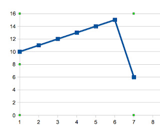
the current profile would look like this
ie each coil is hit with 10 amps and then its dropped back to 10Amps @ 25% Duty Cycle.
at 25% duty cycle the overlap turns out to be quite high.. i would need a PSU that spits out 25Amps @24 volts.. this is closer to reality but still a bit too far off i think.. i guess i will have to see what ebay has to say about the price of fish.. if i can find a 24V psu that is cheaper than further complicating the controller i wil do that other wise i will have to break down the coils into even smaller groups..
UPDATE: -
actually i have made an error.. the curve will look like this
the previous chart didn't take in to account the fact that we will be turning off cells after they have been driven @25% this makes things much more manageable. I can probably stagger out firing order a little more and make the curve a little flatter but this will do for now.. 15Amps @ 24Volts can be had really cheaply thanks to Ebay. just found a buy it now 24volts 20amp PSU Delivered for $66Au Bargain. this PSU allows me to fire two sub sections at once, basically this will allow for upto 33% duty cycle and if managed correctly 100% startup/inrush current can be achieved, the plan will be to turn each coil on for 90% duty cycle for the first pulse and then .1s after that, as the cycle steps thru the first time each coil is energized it will actually be on for 100% for one cycle, 90% + 10% then after that they will be turned on for 10% of the time rotating between the 6 coil subsections i can manage 16.6% duty cycle without overlap. if overlap is used i can get 33.2% duty cycle before my PSU will start to complain.
worst case is that i end up with a nice 20Amp PSU for my printer. I was running the steppers off 24volts but got to tidying things up and switched back to 12volts..
Will post a further update once the controller is done and tested.
If i was to break the bed up into 3 sections of 20 hexagonal cells each section would have a effective resistance of 1/( (1/22) * 20) = 1.1 ohms
Each section of bed would draw @12volts 12/1.1= 10.1 amps of current at 100% duty cycle
but this could be cut back to 2.5 amps once running @25% duty cycle, this could be done with a capacitor charge pump circuit of some sort or i could break each section down further into two this would give me a sectional current draw of 5.05amps @ 100% duty cycle and 1.25amps @25% duty cycle.
if was to run the coils at 24volts (like the good test showed is required) the sectional current draw would be doubled. with 3 sections each drawing 20amps @24volts ( and each sub section drawing 10amps) if i was to turn them all on at once i would need 60Amps of current at 24volts, this is unreasonable. but if i stagger fire each subsection @100% Duty cycle then cut back to 25% duty cycle i would need 10amps then 2.5amps per sub section.
the current profile would look like this
@ 10% Duty Cycle
@ 25% Duty Cycle
at 25% duty cycle the overlap turns out to be quite high.. i would need a PSU that spits out 25Amps @24 volts.. this is closer to reality but still a bit too far off i think.. i guess i will have to see what ebay has to say about the price of fish.. if i can find a 24V psu that is cheaper than further complicating the controller i wil do that other wise i will have to break down the coils into even smaller groups..
UPDATE: -
actually i have made an error.. the curve will look like this
the previous chart didn't take in to account the fact that we will be turning off cells after they have been driven @25% this makes things much more manageable. I can probably stagger out firing order a little more and make the curve a little flatter but this will do for now.. 15Amps @ 24Volts can be had really cheaply thanks to Ebay. just found a buy it now 24volts 20amp PSU Delivered for $66Au Bargain. this PSU allows me to fire two sub sections at once, basically this will allow for upto 33% duty cycle and if managed correctly 100% startup/inrush current can be achieved, the plan will be to turn each coil on for 90% duty cycle for the first pulse and then .1s after that, as the cycle steps thru the first time each coil is energized it will actually be on for 100% for one cycle, 90% + 10% then after that they will be turned on for 10% of the time rotating between the 6 coil subsections i can manage 16.6% duty cycle without overlap. if overlap is used i can get 33.2% duty cycle before my PSU will start to complain.
worst case is that i end up with a nice 20Amp PSU for my printer. I was running the steppers off 24volts but got to tidying things up and switched back to 12volts..
Magnetic Bed progress update
A While ago we made a foot control pedal for his tig welding machine, it was a rather simple affair, a box that hinged at the bottom with a spring inside and s few plastic gears on a POT. this was working well but after working with it my mate asked how hard it would be to add a button to half the range of the pedal, after thinking about it for about 5 seconds i found that we could put a fixed 10k resistor in series with the POT and add a bypass switch that allows us to select from 0-100amps and 0-270amps. the pedal that the manufacturer sells retails for $450au. total cost of our pedal is $32 including the new switch. with this extra fine control my mate was able to tack these together with out collapsing the steel into the area that i just milled out.
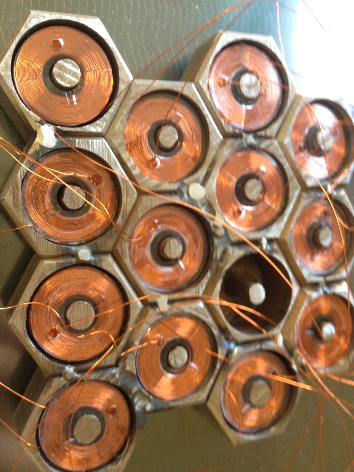
To make this thing work i require 14 (for now) coils that i can energize and create a magnetic field in the right places in these cups.
When i first thought of this idea i had a search on Ebay for some thing that i could wind the wire onto, i ended up selecting standard sewing machine bobbins. these normally are the ones that go under the foot. Most sewing machines have a feature that allows you to load these with cotton thread with great ease, so i thought i would use my mums sewing machine to load the bobbins but she didnt seem to like the idea of enamel wire running through her machine so while i have been waiting for various parts for various projects i have started yet another project, a Coil winder. i thought it would be advantageous for me to have a way to wind coils in a controlled and repeatable manner. I also like to play with coil guns so it would get a great deal of use for that if it has the right features.
I re-appropriated a old test platform that had a stepper motor hooked up to a M3 threaded rod and a pair of guide rails, i then added three rollers to this to guide the wire to the coil form. one guides the wire from the roll in the up and down vector and the other two cross at 90' to each other to allow me to guide the wire to the left or to the right. My thoughts on the coils i need for my coil gun are varied and rather random, i plan to test differently wound coils to work out whats best. so i have started my coil winder with a simple wind program to start with, this is that the wire is loaded in a random fashion with the stepper motor no moving. these bobbins are only 10mm wide so its not needed. later i plan to add a way to wind coils in either direction, left or right hand rule, be able to wind coils from the left or right only, and control how many turns between switching between left and right feeds.
Here you can see the display of the coil winder I have a few fields on the screen that should allow me to do most of what i want, number of turns per layer. number of layers, wire diameter, and a progressive count of whats going on to the coil form.
After a few firmware updates and mods and a really annoying hardware bug that turned out to be me, (had a wire one pin to the left from where i thought i had put it, so weird things were happening). Once I started winding coils I found it rather addictive (ask me again after i make 60 of these). I sized up the cups and the coil forms and did a test run on a sacrificial lamb i found that i can get ~880-900 turns onto the bobbins before they start to hang outside the edges. As i was winding i added a few drops of super glue to the coil to help hold them together while i worked on them.
here is a video of the one of the coils being wound onto the form, the first videos shows you the entire setup the second video shows the last stages of winding. there was a big section in the middle that was boring so i chopped it out..
I put heat shrink over the copper wire making sure the conductors were not shorting out to the cups, i placed a bit of kapton tape around the coil itself to protect them from the sharp edges the cups. I then poked the wires through a 3mm hole that i drilled in the bottom of each cup. when i drilled the holes for the wires i made sure they would come out in between the T slots on the Mill Bed. this will allow me to hold it down by drilling some 4mm holes in the center row to some T nuts.
once i had the wires in place i then mixed up some 2 part epoxy glue, managed to get it everywhere in the process of gluing in each coil, it was a little difficult making sure i pulled the wires nice and tight to make sure they didn't get caught under the coils or at the sides, and not pulling the heat shrink down off the wires, in the end i managed to get the wires and coils all glued in without any problems.
the coils that i ended making have a resistance of about 22ohms each. this kinda works out well. the sacrificial test coil that i made first seemed to cope well with about half an amp of current flowing through it. it did get a little warm after a while (80'c) but that's still well within the specs of the wire. (125'c)
Need to do some testing now. then i will find some epoxy resin that i can pour into/over the coils and cups to provide me with a nice flat surface that i could machine from. but thats only needed if these tests go well.. with each coild taking 6watts each to power up 60 of these could consume some real power. i was reading on the internet the other night that once a coil is energized it only requires 10% of the initiating power to sustain that magnetic filed.. while i am a little skeptical of this claim its worth a test. if i have 13 coils (the astute reader may have noticed already that i knocked a cup off the test bed for other testing..) and I wire them all up in parallel i will end up with 1.6 ohms, If I feed that with 12Volts i should end up with ~ 7 amps. this is quite a bit of power (84watts) if i have to run it at 100% duty cycle. but if i can run that at as little as 10% duty cycle i will only use 8.5 watts.. in theory this will require me to be able to either be able to change the voltage from 12volts to 1.2volts or use PWM. i think PWM is the easiest option a simple 555 timer circuit or a Pic Micro and a Mosfet with a nice big Back EMF clamping diode, should do the job. depending on how many wires i want to use to control the bed i could stagger fire the coils to reduce the load on the PSU. i have many 12v 6Amp PSU's and if i was to stagger fire the coils in groups of four and the 10% Duty Cycle claim turns out to be true i will have no problems at all..
Sunday, 16 December 2012
Some Gcode
I couldn't help myself i had to see if i could write some gcode and see if it would do what i tell it.
what i did was first calculate the circumference of my blank 10mm rod. i then calculated how many teeth and grooves i can cut in to that surface. i worked out that if i have 1mm gaps and 0.75mm peaks i would end up with 17.5 teeth so i did the maths to even that up to 18 teeth. that gives me a 20' rotation between slices that will make my gaps 1mm and leave a peak of 0.74mm between the gaps.
the gcode to do this is specific to my cutter that i have made, it is a 1mm thick cutter with a 3.5mm diameter. if you were to think of a tiny T slot cutter then you are spot on..
G21 #select metric mode
G91 #select incremental referencing
G0 Y-19 F10 # sets up cutter ready to eat metal
G0 Y7 F10 # gets closer to the job
G0 Y3 F0.0005 # moves in for the cut.
G0 Y-10 F10 # move back from job
G0 A20 F10 # rotates job 20' ready for next cut
G0 Y7 F10 # and repeat 17 more times to cut all the teeth.
G0 Y3 F0.0005
G0 Y-10 F10
G0 A20 F10
G0 Y7 F10
G0 Y3 F0.0005
G0 Y-10 F10
G0 A20 F10
G0 Y7 F10
G0 Y3 F0.0005
G0 Y-10 F10
G0 A20 F10
G0 Y7 F10
G0 Y3 F0.0005
G0 Y-10 F10
G0 A20 F10
G0 Y7 F10
G0 Y3 F0.0005
G0 Y-10 F10
G0 A20 F10
G0 Y7 F10
G0 Y3 F0.0005
G0 Y-10 F10
G0 A20 F10
G0 Y7 F10
G0 Y3 F0.0005
G0 Y-10 F10
G0 A20 F10
G0 Y7 F10
G0 Y3 F0.0005
G0 Y-10 F10
G0 A20 F10
G0 Y7 F10
G0 Y3 F0.0005
G0 Y-10 F10
G0 A20 F10
G0 Y7 F10
G0 Y3 F0.0005
G0 Y-10 F10
G0 A20 F10
G0 Y7 F10
G0 Y3 F0.0005
G0 Y-10 F10
G0 A20 F10
G0 Y7 F10
G0 Y3 F0.0005
G0 Y-10 F10
G0 A20 F10
G0 Y7 F10
G0 Y3 F0.0005
G0 Y-10 F10
G0 A20 F10
G0 Y7 F10
G0 Y3 F0.0005
G0 Y-10 F10
G0 A20 F10
G0 Y7 F10
G0 Y3 F0.0005
G0 Y-10 F10
G0 A20 F10
G0 Y7 F10
G0 Y3 F0.0005
G0 Y-10 F10
G0 A20 F10
G0 Y7 F10
G0 Y3 F0.0005
G0 Y-10 F10
G0 A20 F10
%
there you have it rather simple isn't i will post some pictures of what i make and some screen grabs of what the part should look like and you can all have a look and laugh at how different the two are :).
oh also this gcode will only cut one of the three sections that i require for my printer. i do like to make things hard for myself :0
what i did was first calculate the circumference of my blank 10mm rod. i then calculated how many teeth and grooves i can cut in to that surface. i worked out that if i have 1mm gaps and 0.75mm peaks i would end up with 17.5 teeth so i did the maths to even that up to 18 teeth. that gives me a 20' rotation between slices that will make my gaps 1mm and leave a peak of 0.74mm between the gaps.
the gcode to do this is specific to my cutter that i have made, it is a 1mm thick cutter with a 3.5mm diameter. if you were to think of a tiny T slot cutter then you are spot on..
G21 #select metric mode
G91 #select incremental referencing
G0 Y-19 F10 # sets up cutter ready to eat metal
G0 Y7 F10 # gets closer to the job
G0 Y3 F0.0005 # moves in for the cut.
G0 Y-10 F10 # move back from job
G0 A20 F10 # rotates job 20' ready for next cut
G0 Y7 F10 # and repeat 17 more times to cut all the teeth.
G0 Y3 F0.0005
G0 Y-10 F10
G0 A20 F10
G0 Y7 F10
G0 Y3 F0.0005
G0 Y-10 F10
G0 A20 F10
G0 Y7 F10
G0 Y3 F0.0005
G0 Y-10 F10
G0 A20 F10
G0 Y7 F10
G0 Y3 F0.0005
G0 Y-10 F10
G0 A20 F10
G0 Y7 F10
G0 Y3 F0.0005
G0 Y-10 F10
G0 A20 F10
G0 Y7 F10
G0 Y3 F0.0005
G0 Y-10 F10
G0 A20 F10
G0 Y7 F10
G0 Y3 F0.0005
G0 Y-10 F10
G0 A20 F10
G0 Y7 F10
G0 Y3 F0.0005
G0 Y-10 F10
G0 A20 F10
G0 Y7 F10
G0 Y3 F0.0005
G0 Y-10 F10
G0 A20 F10
G0 Y7 F10
G0 Y3 F0.0005
G0 Y-10 F10
G0 A20 F10
G0 Y7 F10
G0 Y3 F0.0005
G0 Y-10 F10
G0 A20 F10
G0 Y7 F10
G0 Y3 F0.0005
G0 Y-10 F10
G0 A20 F10
G0 Y7 F10
G0 Y3 F0.0005
G0 Y-10 F10
G0 A20 F10
G0 Y7 F10
G0 Y3 F0.0005
G0 Y-10 F10
G0 A20 F10
G0 Y7 F10
G0 Y3 F0.0005
G0 Y-10 F10
G0 A20 F10
G0 Y7 F10
G0 Y3 F0.0005
G0 Y-10 F10
G0 A20 F10
G0 Y7 F10
G0 Y3 F0.0005
G0 Y-10 F10
G0 A20 F10
%
there you have it rather simple isn't i will post some pictures of what i make and some screen grabs of what the part should look like and you can all have a look and laugh at how different the two are :).
oh also this gcode will only cut one of the three sections that i require for my printer. i do like to make things hard for myself :0
Progress on the Mill build
Its nearly Christmas,
My mate found time to finish off 90% of the dividing head ( YAY ). I rushed it home with the PC and controller box, attached a power plug that i had been putting off until i had a reason to. Then proceeded to install a copy of ECM running on Ubuntu 10.04 from a liveCD image to a USB key then onto the 4Gb CF card. the motherboard seems to be a little slow booting up so i may sink another $50 into the build and buy a 8GB sata SSD and liberate the processor..
Once I had the OS and EMC installed I Proceeded to attempt to configure EMC. this turned out to be in total a 2 day ordeal. first the problems were getting the LiveCD image to actually boot, just had to find a magical usb key and the right settings in the bios and standing on one foot with one eye closed :).
I purchased the Stepper interface quite a while ago and the exact user manual for my board so i started looking on ebay, i couldn't find the exact seller with the same unit. I did find several that looked the same, but when i downloaded the data sheets for them the pin maps just didn't line up properly, the 5 axis data sheet had the right title and said it was for the 5 axis model but the pin table only showed 4 axis, another had only 3 axis, then finally i found one that had all five axis labeled..
I ran the stepconf program to configure the stepper drivers as per the data sheet, but weird stuff happened, so then i looked at my cable that i have made to go between the par port and the stepper driver, turns out that this was rather wrong, so i turned the ends around about 5 times until i finally got the right orientation so pin 1 is connected to pin 1 and so on. i tested the results and yet another fail, not sure where the problem was i started testing, i grabbed a LED and jammed it in the end of the cable, then clicked on things in the gui and all the pins matched their functions. So then i figured i should probably check the pin functions on the stepper board.. this was a little difficult, i had to first work out which pins would make a led light up then try and work out what that led meant, in the end i managed to get each Axis spinning in both directions when commanded to, some of the axis were being difficult but got there in the end.
At this point in time i have all the Axis responding to the GUI buttons, i have calibrated the XYZ Axis' according to the numbers, leadscrews have 16TPI = 1.558mm/Revolution, 200 steps per rev on the steppers, 1:1 drive ratio and 2:1 microsteps. this results in 251.9steps/mm. for the Dividing head it has 200 steps per rev, 1:3 ratio, and 16:1 microsteps, resulting in 26.7 steps per degree, this should be fine enough for what i want to play with. I should be able to cut some gears and worms, but first on the list is a triple hyena bolt. Arcol from the reprap forums has designed a really nice drive bolt that grips the plastic really well and doesn't clog up, i have asked in the past if he could make me a custom one that has three sets of teeth but at the time it wasn't worth his time as he gets his bolts that he sells made in a workshop by real machinists if anyone is wondering what sort of bolt they should use see Arcol's blog.
Before i have even bolted all the bits on to the mill i already want to program it... I want to write some gcode that will cut my bolt :) there are a few parameters that i will have to get from the Mill itself for the code to be complete but i will write it anyway, have i mentioned before i am an impatient and impulsive sort of person...
next post some Gcode to cut a Drive bolt..
here you can see the dividing head sitting on the X axis, my mate made me a Angle bracket to mount the head to the bed as shown above, or to have the head pointing up so you could drill or slot a gear as well as cut the teeth.
here you can see how chunky it is compared to the rest of the mill. we should have no bounce or flex when this is mounted in either position. hanging out the side of the bed there you can see the profile piece that is becoming T nuts :)
here is a close up of the belt and pulley. in testing i have done on the bench here this little chuck has some torque behind it. the steppers are 269 ounce with a 3:1 ratio on it that should come out at over 60netwons/meter. that could be more torque than on the other axis :)
My mate found time to finish off 90% of the dividing head ( YAY ). I rushed it home with the PC and controller box, attached a power plug that i had been putting off until i had a reason to. Then proceeded to install a copy of ECM running on Ubuntu 10.04 from a liveCD image to a USB key then onto the 4Gb CF card. the motherboard seems to be a little slow booting up so i may sink another $50 into the build and buy a 8GB sata SSD and liberate the processor..
Once I had the OS and EMC installed I Proceeded to attempt to configure EMC. this turned out to be in total a 2 day ordeal. first the problems were getting the LiveCD image to actually boot, just had to find a magical usb key and the right settings in the bios and standing on one foot with one eye closed :).
I purchased the Stepper interface quite a while ago and the exact user manual for my board so i started looking on ebay, i couldn't find the exact seller with the same unit. I did find several that looked the same, but when i downloaded the data sheets for them the pin maps just didn't line up properly, the 5 axis data sheet had the right title and said it was for the 5 axis model but the pin table only showed 4 axis, another had only 3 axis, then finally i found one that had all five axis labeled..
I ran the stepconf program to configure the stepper drivers as per the data sheet, but weird stuff happened, so then i looked at my cable that i have made to go between the par port and the stepper driver, turns out that this was rather wrong, so i turned the ends around about 5 times until i finally got the right orientation so pin 1 is connected to pin 1 and so on. i tested the results and yet another fail, not sure where the problem was i started testing, i grabbed a LED and jammed it in the end of the cable, then clicked on things in the gui and all the pins matched their functions. So then i figured i should probably check the pin functions on the stepper board.. this was a little difficult, i had to first work out which pins would make a led light up then try and work out what that led meant, in the end i managed to get each Axis spinning in both directions when commanded to, some of the axis were being difficult but got there in the end.
At this point in time i have all the Axis responding to the GUI buttons, i have calibrated the XYZ Axis' according to the numbers, leadscrews have 16TPI = 1.558mm/Revolution, 200 steps per rev on the steppers, 1:1 drive ratio and 2:1 microsteps. this results in 251.9steps/mm. for the Dividing head it has 200 steps per rev, 1:3 ratio, and 16:1 microsteps, resulting in 26.7 steps per degree, this should be fine enough for what i want to play with. I should be able to cut some gears and worms, but first on the list is a triple hyena bolt. Arcol from the reprap forums has designed a really nice drive bolt that grips the plastic really well and doesn't clog up, i have asked in the past if he could make me a custom one that has three sets of teeth but at the time it wasn't worth his time as he gets his bolts that he sells made in a workshop by real machinists if anyone is wondering what sort of bolt they should use see Arcol's blog.
Before i have even bolted all the bits on to the mill i already want to program it... I want to write some gcode that will cut my bolt :) there are a few parameters that i will have to get from the Mill itself for the code to be complete but i will write it anyway, have i mentioned before i am an impatient and impulsive sort of person...
next post some Gcode to cut a Drive bolt..
here you can see the dividing head sitting on the X axis, my mate made me a Angle bracket to mount the head to the bed as shown above, or to have the head pointing up so you could drill or slot a gear as well as cut the teeth.
here you can see how chunky it is compared to the rest of the mill. we should have no bounce or flex when this is mounted in either position. hanging out the side of the bed there you can see the profile piece that is becoming T nuts :)
Subscribe to:
Posts (Atom)