Showing posts with label Reprap. Show all posts

Sunday, 27 January 2013

WOOT I'm so happy i'm squirting... plastic all over the place

    I have spent the last 36 or so hours poking at my printer trying to get it to play nice..  Last night i was so close to getting nice results out of the beast...

    After printing and tweaking and printing and tweaking and printing some more, I just couldn't get it right. the first layer was too thick the middle layers were too thin and the top layers too thick, then i decided to check what i was working with, turns out what i thought was a 0.5mm nozzle was actually a 0.35mm nozzle.. after that things went pear shape, so i went to bed, that was about 5am..

   when i woke up i had another stab at it. looking at what i had done made no sense, the firmware changes i made were gone, or wrong... so i started fresh, looked at the output and started to make some progress. i found that i needed to install the Z min endstop, to get a bit of repeatability out of the printer, once this was done things started to get better, i got the printer to start printing nice, then they wold fail due to the print job lifting up off the print bed... once i adjusted the temp of the bed to get 110'c on the surface of the glass, and the fans to blow at the right time, things started to come together really well. well enough that i could get to chasing down some print quality.

    With Repraps and Repstraps the fun and games really start when you start calibrating, and chasing print quality. You could be starting the print too close to the bed, (is there backlash in you z axis), adjust your Z offset in the slicer to test this then adjust the hardware to zero this out. then you need to make sure you are putting out just the right amount of plastic. When things don't come out  as expected there are a variety of causes, are you moving your axis enough, or too much for a desired gcode command.  I got to the point where the side of my test cube were nice but the corners where the print head lifts up and down between layers were not really pretty, there were random blobs, not on every layer, this is because Slic3r has a feature to randomize the starting point of each layer. i got the blobs small but it wasn't as good as i wanted, then trouble started, i got something stuck in the nozzle, i tried the lazy way out and created more work for myself, i tried to clear the hole by drilling the hole out to 0.5mm but ended up snapping the drill in the nozzle and stuffed it..

     Tomorrow is A Long weekend  here in Australia so i am going to spend the day at my mates workshop and knock up another three new 0.5mm nozzles, if time is going well i will make a bunch of blanks up as spares then when the 0.25mm & 0.35mm drills arrive from ebay i will drill them out. to do this i might have to re-face the jaws on my dividing head, while making my hyena style bolt up i noticed that depending on where the job is inserted into the jaws it can wobble, this didn't affect my bolt as i used a tailstock steady on the job.


Here you can see the results of my 36hour printing session.... on the left lots of worms. the back row, some niceish blocks. and in the middle you can see a print with a missed step. and on the lower right the nicest print so far.. that crease in the top is from where the extruder clipped it while it was still soft when i was trying to move the print head out of the way..  this is not perfect it still has a few blobs here and there but its on the way to being nice.. cant wait to make some more nozzles..

I still have some ptfe tube and brass left over from the last time when i made the first lot. this time i will make them a little longer and see if that helps with some of the problems have been having. and this time i have the CNC mill working enough that i wont have to hand crank the drill bit in and out to peck drill the hole to prevent snapping.. its a pain as you have to pull the drill bit all the way out of the job to check you have not snapped it, a 0.5mm drill bit doesn't give you very much if any feedback, and if you snap a drill when blind drilling or are unsure, you can waste drill bits trying to drill out the hole that is now blocked by a drill. will have to make some sort of depth ring for the drill bits to make my life easier..

for now its a bit of TV and Bed for me..

Tuesday, 22 January 2013

Victory is Near... so near i can taste the plastic!!

Had a hard day at work trying to make some soothing sounds from a PIC micro and a mosfet driven speaker, feeding it a square wave at varying frequencies to make a bleep and a bloop sound for good and bad report. I was eager to get to the mill, as soon as i sat down at home i rang my mate to see if he has finished work for the day, and he was, so i scooted out there as fast as traffic would allow. I got there at about 6:30ish and proceeded to setup the mill to enable the Y axis as i am still waiting on the replacement stepper drivers, so i am plugging the A axis into a axis that is not required, this time i needed the Y axis, first time i needed to use it so i had to calibrate the axis and document the backlash.  after about and hour or so and nice hunk of chicken i had the axis' setup and ready to roll.

i whipped up some gcode to make the teeth that i need, forgetting my notebook that i scribbled the formula in last night i had to go off memory and plain forgot how many teeth i wanted and some how ended up only cutting 18 teeth on the first groove so i manually cnc'd the last two teeth.

%
G21
G91
o100 repeat [20]
G1 Y-2.6 F25
G1 Y2.6 F50
G1 A18 F1000
o100 endrepeat
%

this fed the cutter into the groove nice and slowly then retreats to clear the job and rotates 18' and repeats. simple code. i then manually cranked the X axis to line up with the next groove and let it rip and repeated this for the last groove. the teeth are a little off center to the grooves but that shouldn't affect anything as i pre-grooved the job.

so now i need to go to jaycar.com.au and buy me a 10 tooth gear to mesh with the worm drive and mount that. i will venture into hobbyco in the city to latch onto a new set of skateboard bearing ( i know i have four fresh ones here somewhere but meh) then i will be all set to start a print, i seem to have lost one of my nozzles, probably hiding with the bearings so i might order some 0.25mm & 0.35mm drills and make a new set or two, now i have the mill under control they wont take so long to make, well at least i wont have to crank it by hand to peck drill them out, last time it was a PITA, might have a better look in the work room.. once i have the hardware sorted i will have to find out what the best firmware will be to use, i haven't been in #reprap for a while..

here is a vid or two of the bolt being machined on my cnc X2 Sieg mill with Dividing head..


 here you can see the cutter making the teeth for the drive bolt for my 3d printer. its cutting 20 teeth.

 this is the cutter that i made from a piece of 5mm hss tool steel that i bought off the internet for about 1$au each, bought 10 bits in the buy it now sale, so $10 delivered, i have posted about a company that will make/does make, cutters that would have done the job but i am an impatient sort of person and wanted to try and see if i could do it, as it turns out its not that hard i used a 6inch angle grinder with a 1mm cutting disc to form the profile then turned it to an angle of about 30' in the tilting vice to cut the cutting edges/flutes.
 my iphone doesn't seem to like taking photos of things up close but the videos are not that bad..

the cutter seems to have survived enough that i will probably use it to make the new extruder with any improvements that i can think of. i would like to see if i could make this thing printable and post it to thingiverse.com, that reminds me i should update my existing things i have posted to reflect the progress that has been made. 


Sunday, 18 September 2011

Progress Update 3

It's been a productive few days, the plan changed slightly, only the threaded rods for Z axis comes off the main frame, all smooth rods are welded into place and bearings cannot be changed, Meh...


So at the moment i have all the motors mounted, with their pulleys attached and their respective idle pulleys. The Z axis is all bolted up and the lead screws and motors all turn very easily by hand, i have attached a few spare gears from the old setup to the tops of the motors to allow easy adjustment.

The Y axis bed frame is welded and bolted to the bearings, The same for the X axis, all the axis run really nice and smooth they don't free run when you push them but they all move with a single finger.

Next i have to attach the belts 2 for  each X and Z axis. this will hopefully this will keep the carriages nice and square and allow them to roll nice.

I will have to stop at the hardware and get some screw in rubber feet for the base of the frame to keep the Y axis from hitting the motor i have had to mount it about 10mm lower then the bottom of the frame, so at the moment that end of the frame is resting on the motor mount, this will be resolved with some standoff feet. They will also help keep the noise from the table vibrating.

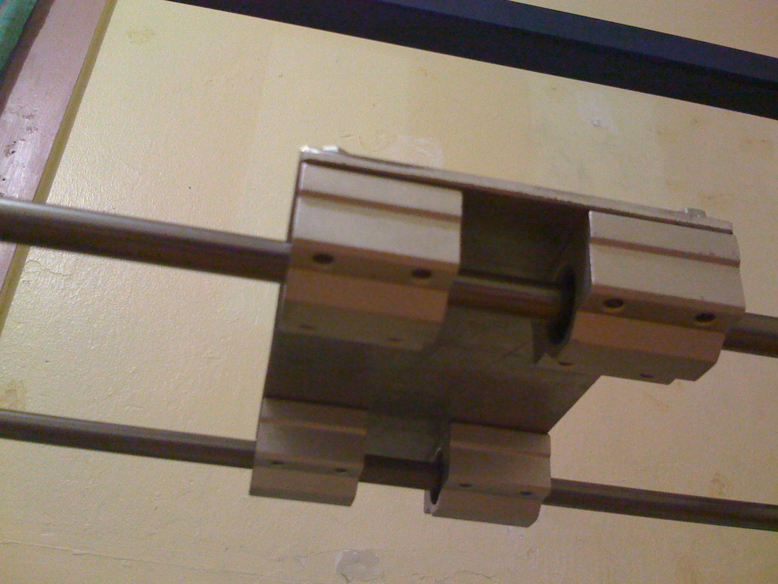
 Under Shot of the X carriage.
 Top Shot of the X carriage plate.
 Shot showing the lead screws coupling to the Z motors.
 Y Axis motor with T5 20teeth pulleys.
 X Axis Motor with pulley, same as Y axis.

 Where X meet Z axis. and X axis idle pulleys.
 Another overall shot you can just see in the top of this picture the gears i have mounted to the Z axis to allow easy adjustments. I have also placed the old Glass bed that the previous printer used as a print bed. this new printer is has a bed that's twice the size of the old bed, but will be able to take another bed that's twice this size. this frame is square with 478mm sides and  677mm diagonals. the longer bed will be 800mm+ long with the same width.

The Z axis was an absolute bitch to install, even though the entire printer was welded pretty much in situ we moved the bearings so the TIG welding didn't cook the goodness out of them, this allowed things to move. It was almost like they were welded under tension, but i know this was not the case. So i persevered, I had to file 1mm clearance extra around the vertical smooth rods as the X frame seemed to have gotten a little wider, this solved half the problem, next i had to bend the bracket that holds the captive nut for Z so the threaded rod would run that little bit smother. Then everything went together really nice, rather annoyed at myself for leaving the belt at my mates work shop. My boss probably thinks its a good thing as i will get a good night sleep instead of working on the printer until i get movement :) so i will go to the workshop tomorrow buy a few mice and feed the snake while i am at it, he is really hungry and then see about attaching the belts, that reminds me i also left the tension springs there too.

Now that i have this much done i am questioning the design of the Triple extruder that i have been planing to use from the old printer, it seems like it going to be rather difficult to install with out it interfering or limiting my print size too much, every way i look at it, it doesn't seem to fit, That was a prototype, and never was intended for long time service, there are too many little things i am not happy with on it, so i may take this opportunity to start the Triple extruder MK2. a lower profile version that may even be print able. to get to use all of the current print bed i am going to have to cut some arches out of the X carriage plate to clear the lead screws and bearings on the Z axis.  

Thursday, 8 September 2011

Not much going on..

So not much progress on the printer we are waiting for the weekend so we have some space in my mates workshop, All we have to do is drill some 10mm holes for the dowels to be welded into.

So i thought i might describe my plans on how i am going to drive my axis'. The Z axis has two motors on it, these are rather large  KL-23-251-24-8B Nema 23 motors that have ~0.6Nm they will have no issues picking up a few kilograms between them with the 1/2inch threaded rods and linear bearings. I have also used the same motors for my X & Y axis but these are being driven by 24Volts (Z axis is 12volts) hopefully the extra voltage will result in more Speed!!

To help try and make things runs smooth i will be using two belts on each axis. The motors i bought have the axles 25mm out each end, i have purchased 8 T5 15tooth pulleys and 5meters of belt, i think i am going to be short on belt and have to order some more. The main reason i want to use two belts is to ensure that the bed is pulled evenly and not jam the linear bearings, as X is a little narrower i don't need to use two belts but it makes things easier if i do. It allows me to mount the motor sort of centered.

Currently when I have been playing with the axis' if i try and move them by holding the ends of the aluminum bars the bearings jam, but if i apply the pressure in the middle a single finger can roll them back and forward, I think I should be fine with two belt, this also keeps the center of the X plate clear for the extruder to live.